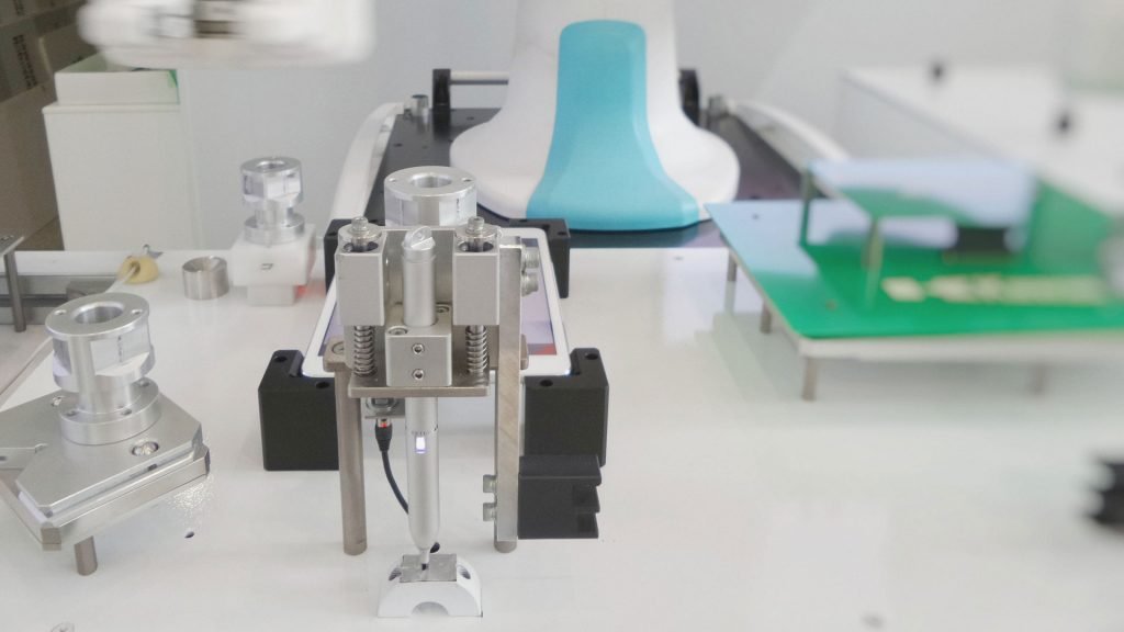
Linear motion systems are ready to install guide and drive systems which gives excellent performance in compact dimensions. They have a variety of configurations such as belt, screw, and roller guides. These systems are capable of handling any loads and cover any travel distances as well as environments.
You can design linear motion systems if you have a certain level of expertise. Whether you decide to design and create from the start using standard parts, following the right choices can help keep things moving. If you want to create your linear motion systems, using Linear Motioneering (a web-based sizing and selection tool) will help you in certain ways. Here’s how to make the most out of Linear Motioneering.
Step 1
Choose any orientation based on the application at first. Then choose the mounting configuration out of the options, fully supported, end supported, or intermittently supported.
Step 2
Now, enter the stroke length from a hard stop. Select a framework for defining the position based on accuracy, repeatability, or allowable backlash. Set the value.
Step 3
If you know the conditions will be crucial for choosing the right material, lubrication scheme, and cover strategy. Then select clean water or chemical spray, press application, moderate to heavy dust-particle count. The application will recommend linear slide options, such as chrome plated and stainless steel, CR linear bearing, or polymer plain bearings.
Step 4
The load is the weight supported by a carrier or saddle supports which includes the payload, fixturing, and tooling. Now, enter the three coordinates (X, Y, and Z). You can also record an applied force that the tool assumes acts at the center of gravity of the load.
Step 5
Now enter the moving distance and time with dwell time which the tool will then convert into acceleration rates. Now, choose a system from the list of the tools present. The tool creates move profiles that are necessary for the selected systems, for example, a maximum-acceleration profile of red, green, and in between. After that choose your preferred profile and acceleration rate. Choosing your acceleration rate will be applicable now. The tool calculates factors like safety factors, bearing and drive loads and the speed of ball and screw.
Step 6
Choose accessories like motor mounts, covers, limits switches, gearheads, and brake. When you are done choosing the accessories. Now, you can download a 3D CAD model of the system in your desired file format. After that save the application or requests in a quote.
Conclusion
When you are preferring whether to make or build you need to think about the engineering time and based on your expertise. You will need to calculate linear and radial-bearing life, ball-screw life, ball-screw critical speed, and other contributing factors. Another advantage of making a home-based linear system is you can monitor the costing.
Buying the system, however, if you don’t have the level of building experience buying the system will help you.


